filmov
tv
Gate Diagram
0:03:18
Basic logic gate timing diagram/ waveform of basic logic gate/digital electronics
0:08:23
Drawing Logic Gates From Boolean Expressions | Important Questions 4 | Digital Electronics
0:29:44
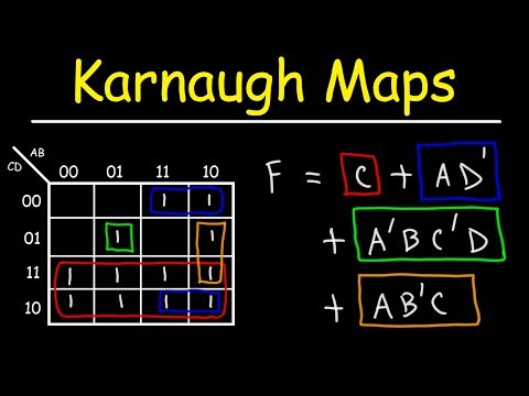
Introduction to Karnaugh Maps - Combinational Logic Circuits, Functions, & Truth Tables
0:02:23
The circuit diagram shown here corresponds to the logic gate | #asdphysics | #asdphysicsacademy
0:00:20
new sliding pro serious photo cell connection /wiring diagram #automation #gateautomation #gate
0:09:35
Constructing Truth Tables for Combinational Logic Circuits
0:17:42
What is Logic Gate? full Explanation | AND, OR, NOT, NAND, NOR, XOR & XNOR Gates
0:00:37
zener dioad ka kam
0:08:24
NAND Gate - Circuit Diagram and Truth Table - Logic Gates - Application of Electronics Class 12
0:08:28
EX-OR Gate - Circuit Diagram and Truth Table - Logic Gates - Application of Electronics Class 12
0:22:10
Diode Logic Gates - OR, NOR, AND, & NAND
0:09:38
NOR Gate - Circuit Diagram and Truth Table - Logic Gates - Application of Electronics Class 12
0:06:22
Find Boolean Equation and Truth Table from Logic Diagram
0:08:21
Ladder diagram for X-OR gate logic (Ladder diagram for Exclusive OR gate logic)
0:05:28
Logic Gates - AND Gate Symbol Truth table Timing Diagram Waveform Explained in English
0:06:58
NOT Gate - Circuit Diagram and Truth Table - Logic Gates - Application of Electronics Class 12
0:10:22
How to Design a Logic Circuit Using Diagrams.net - Logic Gates Diagram Computer Science Tutorial
0:52:40
Schematic diagram and layout of two input NOR gate
0:02:39
HOW TO DRAW A CIRCUIT DIAGRAM USING LOGIC GATES? | PROPOSITIONAL LOGIC (PART 4) | ISC CLASS 11
0:04:34
|Timing Diagram for two input OR Gate| Digital Electronics|
0:11:34
CMOS | 2-input NAND and NOR gates | Layout diagram | VLSI | Lec-34
0:09:30
OR Gate - Circuit Diagram and Truth Table - Logic Gates - Application of Electronics Class 12
0:04:27
Sequence Diagram in UML | Software Engineering
Вперёд
 0:03:18
 0:08:23
 0:29:44
 0:02:23
 0:00:20
 0:09:35
 0:17:42
 0:00:37
 0:08:24
 0:08:28
 0:22:10
 0:09:38
 0:06:22
 0:08:21
 0:05:28
 0:06:58
 0:10:22
 0:52:40
 0:02:39
 0:04:34
 0:11:34
 0:09:30
 0:04:27